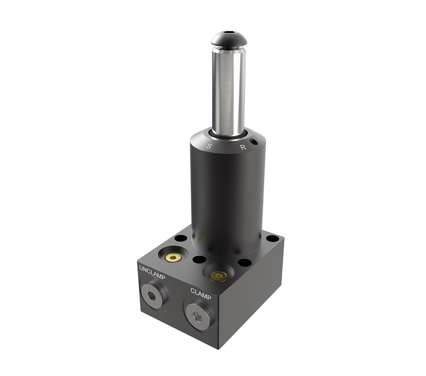
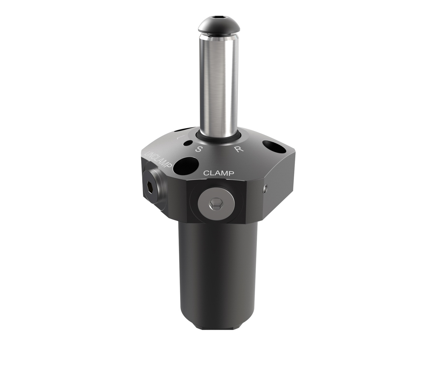
Bottom Flange Swing Cylinders
Jergens Bottom Flange Swing Cylinders offer versatility as a through-hole bottom mount or top plate mounting device.
Features, Benefits, & Product Specifications:
-
Clamping Capacity: 1,100 lbs. - 5,000 lbs. Max.
-
Manifold mounting or standard plumbing
-
Single & Double Acting available
-
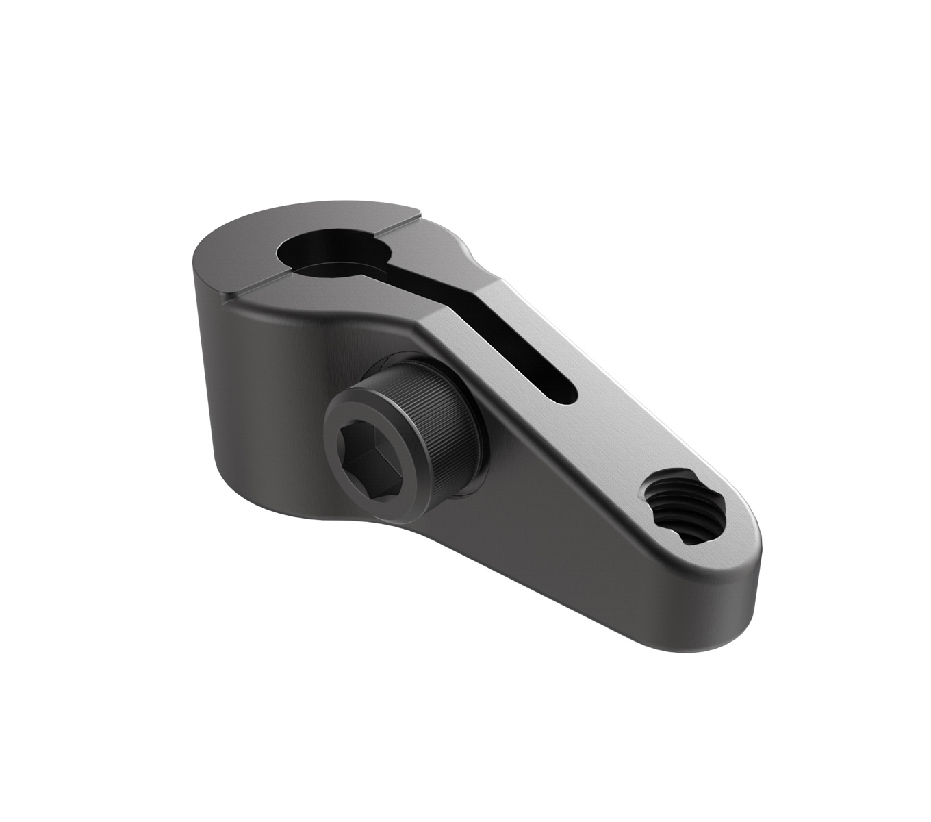
Highly adaptable flange mount design (Clamping Arms sold separately)
Note(s):
- The piston rotates 90° to the right, but may be ordered with 90° left rotation (add -LH to clamp part number) or no rotation (add -SP to clamp part number).
- WARNING: All Swing Cylinders must be used with Flow Limit Valves to dampen the rotating action.
- CAUTION: Don't allow the swing arm to contact the workpiece or fixture while rotating.
Bottom Flange Swing Cylinders

Select a part number for CAD drawings, price and stock availability.
| Part Number | CAD | Unit | Style | A | B | C | D | E | F | G | H | I | J | K | L | M | N | O | P | Q | R | S | Sw. Arm Mounting Hole T | Repair Kit Part Number | Maximum Output Force | Stroke Total | Stroke Rotating | Stroke Clamping | Op. Volume Clamp | Op. Volume Unclamp | Minimum Operating Pressure (psi) | Maximum Operating Pressure (psi) | Effective Piston Area |
|---|---|---|---|---|---|---|---|---|---|---|---|---|---|---|---|---|---|---|---|---|---|---|---|---|---|---|---|---|---|---|---|---|---|
| 60661 |
|
Inch | Single Acting | 1.50 | 0.623 | 0.28 | 0.63 | 2.40 | 1.25 | 5.29 | 2.50 | 0.75 | 0.56 | 2.00 | 1.00 | 0.81 | 0.99 | 0.56 | 0.56 | 1.13 | 0.66 | 0.136 | 3/8-24 x 5/8 | 62360 | 1,100 lbs | .79 in | .45 in | .31 in | .23 in3 | N/A in3 | 750 psi | 5,000 psi | .30 |
| 60663 |
|
Inch | Single Acting | 1.87 | 0.874 | 0.34 | 0.63 | 3.18 | 1.25 | 6.78 | 3.00 | 0.94 | 0.69 | 2.50 | 1.25 | 1.00 | 1.21 | 0.75 | 0.75 | 1.25 | 1.00 | 0.196 | 1/2-20 x 3/4 | 62362 | 2,600 lbs | 1.16 in | .64 in | .52 in | .72 in3 | N/A in3 | 750 psi | 5,000 psi | .62 |
| 60665 |
|
Inch | Single Acting | 2.50 | 1.247 | 0.41 | 0.74 | 4.39 | 1.50 | 9.34 | 3.39 | 1.27 | 0.94 | 3.12 | 1.56 | 1.25 | 0.75 | 1.38 | 1.38 | 0.196 | 5/8-18 X 1 | 62364 | 5,000 lbs | 1.66 in | 1.03 in | .63 in | 1.98 in3 | N/A in3 | 750 psi | 5,000 psi | 1.18 | ||
| 60671 |
|
Inch | Double Acting | 1.50 | 0.623 | 0.28 | 0.63 | 2.40 | 1.25 | 5.47 | 2.48 | 0.75 | 0.56 | 2.00 | 1.00 | 0.81 | 0.99 | 0.56 | 0.56 | 1.13 | 0.66 | 0.136 | 3/8-24 X 5/8 | 62360 | 1,100 lbs | .76 in | .45 in | .31 in | .23 in3 | .46 in3 | 500 psi | 5,000 psi | .30 |
| 60673 |
|
Inch | Double Acting | 1.87 | 0.874 | 0.34 | 0.63 | 3.18 | 1.25 | 6.78 | 3.00 | 0.94 | 0.69 | 2.50 | 1.25 | 1.00 | 1.21 | 0.75 | 0.75 | 1.25 | 1.00 | 0.196 | 1/2-20 x 3/4 | 62362 | 2,600 lbs | 1.16 in | .64 in | .52 in | .72 in3 | 1.43 in3 | 500 psi | 5,000 psi | .62 |
| 60675 |
|
Inch | Double Acting | 2.50 | 1.247 | 0.41 | 0.74 | 4.39 | 1.50 | 9.34 | 2.12 | 1.27 | 0.94 | 3.12 | 1.56 | 1.25 | 0.75 | 1.38 | 1.38 | 0.196 | 5/8-18 x 1 | 62364 | 5,000 lbs | 1.66 in | 1.03 in | .63 in | 1.98 in3 | 4.00 in3 | 500 psi | 5,000 psi | 1.18 |
| Part Number | CAD | Unit | A | B | C | D | E | F | G |
|---|---|---|---|---|---|---|---|---|---|
| 60661 |
|
Inch | 1.540 | 1/4-20 | 0.560 | 0.990 | 0.810 | 1.130 | 0.562 |
| 60663 |
|
Inch | 1.920 | 5/16-18 | 0.690 | 1.210 | 1.000 | 1.250 | 0.750 |
| 60665 |
|
Inch | 2.550 | ./8-16 | 0.940 | 1.250 | 1.375 | 0.750 | |
| 60671 |
|
Inch | 1.540 | 1/4-20 | 0.560 | 0.990 | 0.810 | 1.130 | 0.562 |
| 60673 |
|
Inch | 1.920 | 5/16-18 | 0.690 | 1.210 | 1.000 | 1.250 | 0.750 |
| 60675 |
|
Inch | 2.550 | ./8-16 | 0.940 | 1.250 | 1.375 | 0.750 |
Documents and Videos
Operating Manual
Operating Manual - 81600 ONLY
Jergens Production Vise System
Jergens Production Vises Features and Benefits
Vertical Machine Solutions
Horizontal Machine Solutions
Hydraulic Production Vises
Production Vises


