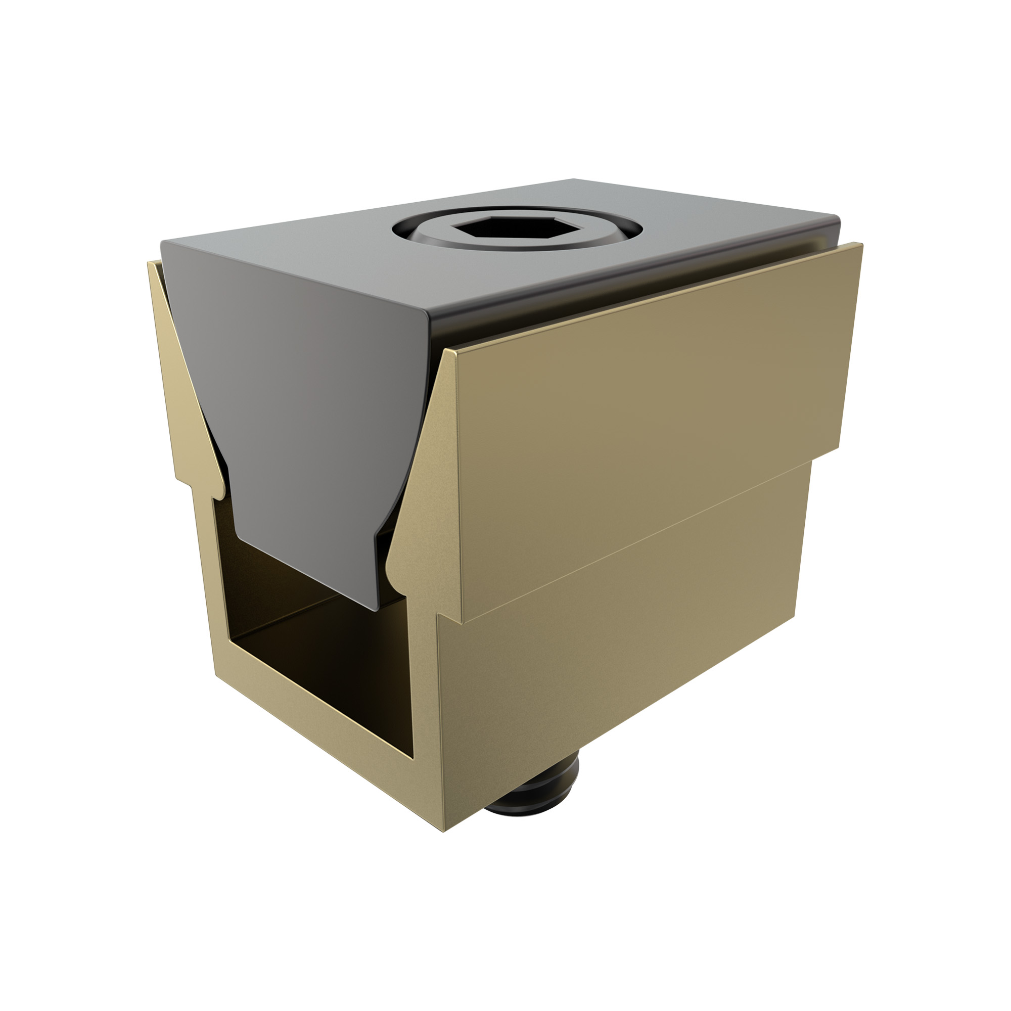
Micro™ Expanding Machinable Clamps
Jergens Micro™ Expanding Machinable Clamps are available with extra material on the clamping jaw so they can be machined to conform to the shape of your workpiece - enabling you to fixture unusual applications easily. The specially designed steel wedge spreads the clamping force uniformly on both sides of the aluminum channel. A unique locking plate is provided to make the clamp rigid while machining the jaw to your specifications, without vibration.
Features, Benefits, & Product Specifications:
-
Material: Channel 7075-76 Aluminum
-
Compact design
-
Allows more parts to be mounted on a fixture
-
Mounting screws included
Note(s):
-
Locking plate is used only to machine jaws. Remove to clamp the workpiece.
-
For the "A" dimension: The distance needed between workpieces for clamp clearance, drill, and tap mounting holes in the center of the “A” dimension.
- The "F" dimension is the amount of machinable stock on jaws.

Micro™ Expanding Machinable Clamps


Select a part number for CAD drawings, price and stock availability.
| Part Number | CAD | Unit | Locking Plate | A (In) | B (In) | C (In) | D (In) | E (In) | F (In) | G (In) | Mounting Screw H | I | Maximum Holding Force (lbs) | Recommended Expansion Stroke (In) |
|---|---|---|---|---|---|---|---|---|---|---|---|---|---|---|
| 68770 |
|
Inch | Yes | 1.125 | 0.50 | 0.62 | 0.420 | 0.18 | 0.18 | 0.400 | 2-56 | 8-32 | 500 | 0.015 |
| 68771 |
|
Inch | No | 1.125 | 0.50 | 0.62 | 0.420 | 0.18 | 0.18 | 0.400 | 2-56 | 8-32 | 500 | 0.015 |
| 68772 |
|
Inch | Yes | 1.500 | 0.75 | 0.94 | 0.632 | 0.37 | 0.26 | 0.624 | 6-32 | 1/4-20 | 1500 | 0.015 |
| 68773 |
|
Inch | No | 1.500 | 0.75 | 0.94 | 0.632 | 0.37 | 0.26 | 0.624 | 6-32 | 1/4-20 | 1500 | 0.015 |
| 68774 |
|
Inch | Yes | 2.000 | 1.00 | 1.25 | 0.820 | 0.50 | 0.39 | 0.812 | 6-32 | 5/16-18 | 2000 | 0.020 |
| 68775 |
|
Inch | No | 2.000 | 1.00 | 1.25 | 0.820 | 0.50 | 0.39 | 0.812 | 6-32 | 5/16-18 | 2000 | 0.015 |
| 68776 |
|
Inch | Yes | 3.000 | 1.50 | 1.87 | 1.215 | 0.75 | 0.62 | 1.200 | 10-32 | 1/2-13 | 3500 | 0.030 |
| 68777 |
|
Inch | No | 3.000 | 1.50 | 1.87 | 1.215 | 0.75 | 0.62 | 1.200 | 10-32 | 1/2-13 | 3500 | 0.030 |
| 68778 |
|
Inch | Yes | 4.000 | 2.00 | 2.50 | 1.625 | 1.00 | 0.80 | 1.625 | 1/4-20 | 5/8-11 | 6000 | 0.040 |
| 68779 |
|
Inch | No | 4.000 | 2.00 | 2.50 | 1.625 | 1.00 | 0.80 | 1.625 | 1/4-20 | 5/8-11 | 6000 | 0.040 |
| 68870 |
|
|||||||||||||
| 68872 |
|
|||||||||||||
| 68874 |
|
|||||||||||||
| 68876 |
|
|||||||||||||
| 68878 |
|
| Part Number | CAD | Unit | Locking Plate | A (mm) | B (mm) | C (mm) | D (mm) | E (mm) | F (mm) | G (mm) | Mounting Screw H | I | Maximum Holding Force (N) | Recommended Expansion Stroke (mm) |
|---|---|---|---|---|---|---|---|---|---|---|---|---|---|---|
| 68770 |
|
|||||||||||||
| 68772 |
|
|||||||||||||
| 68774 |
|
|||||||||||||
| 68776 |
|
|||||||||||||
| 68778 |
|
|||||||||||||
| 68870 |
|
Metric | Yes | 28.6 | 12.7 | 15.7 | 10.67 | 6.3 | 4.6 | 10.16 | M2 | M4 | 2224 | 0.4 |
| 68871 |
|
Metric | No | 28.6 | 12.7 | 15.7 | 10.67 | 6.3 | 4.6 | 10.16 | M2 | M4 | 2224 | 0.4 |
| 68872 |
|
Metric | Yes | 38.1 | 19.1 | 23.9 | 16.05 | 9.4 | 6.6 | 15.87 | M4 | M6 | 6670 | 0.4 |
| 68873 |
|
Metric | No | 38.1 | 19.1 | 23.9 | 16.05 | 9.4 | 6.6 | 15.87 | M4 | M6 | 6670 | 0.4 |
| 68874 |
|
Metric | Yes | 50.8 | 25.4 | 31.8 | 20.83 | 12.7 | 9.9 | 20.62 | M4 | M8 | 8895 | 0.6 |
| 68875 |
|
Metric | No | 50.8 | 25.4 | 31.8 | 20.83 | 12.7 | 9.9 | 20.62 | M4 | M8 | 8895 | 0.6 |
| 68876 |
|
Metric | Yes | 76.2 | 38.1 | 47.5 | 30.86 | 19.1 | 15.7 | 30.48 | M5 | M12 | 15565 | 0.8 |
| 68877 |
|
Metric | No | 76.2 | 38.1 | 47.5 | 30.86 | 19.1 | 15.7 | 30.48 | M5 | M12 | 15565 | 0.8 |
| 68878 |
|
Metric | Yes | 101.6 | 50.8 | 63.5 | 41.28 | 25.4 | 20.3 | 41.28 | M6 | M16 | 26690 | 1.1 |
| 68879 |
|
Metric | No | 101.6 | 50.8 | 63.5 | 41.28 | 25.4 | 20.3 | 41.28 | M6 | M16 | 26690 | 1.1 |
Documents and Videos
 Operating Manual
- Operating Manual - 81600 ONLY
- Jergens Production Vise System
- Jergens Production Vises Features and Benefits
- Vertical Machine Solutions
- Horizontal Machine Solutions
- Hydraulic Production Vises
- Production Vises