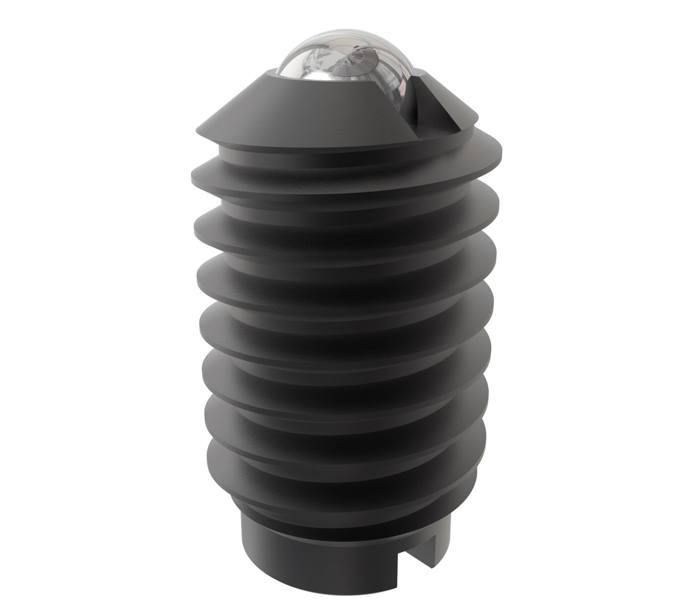
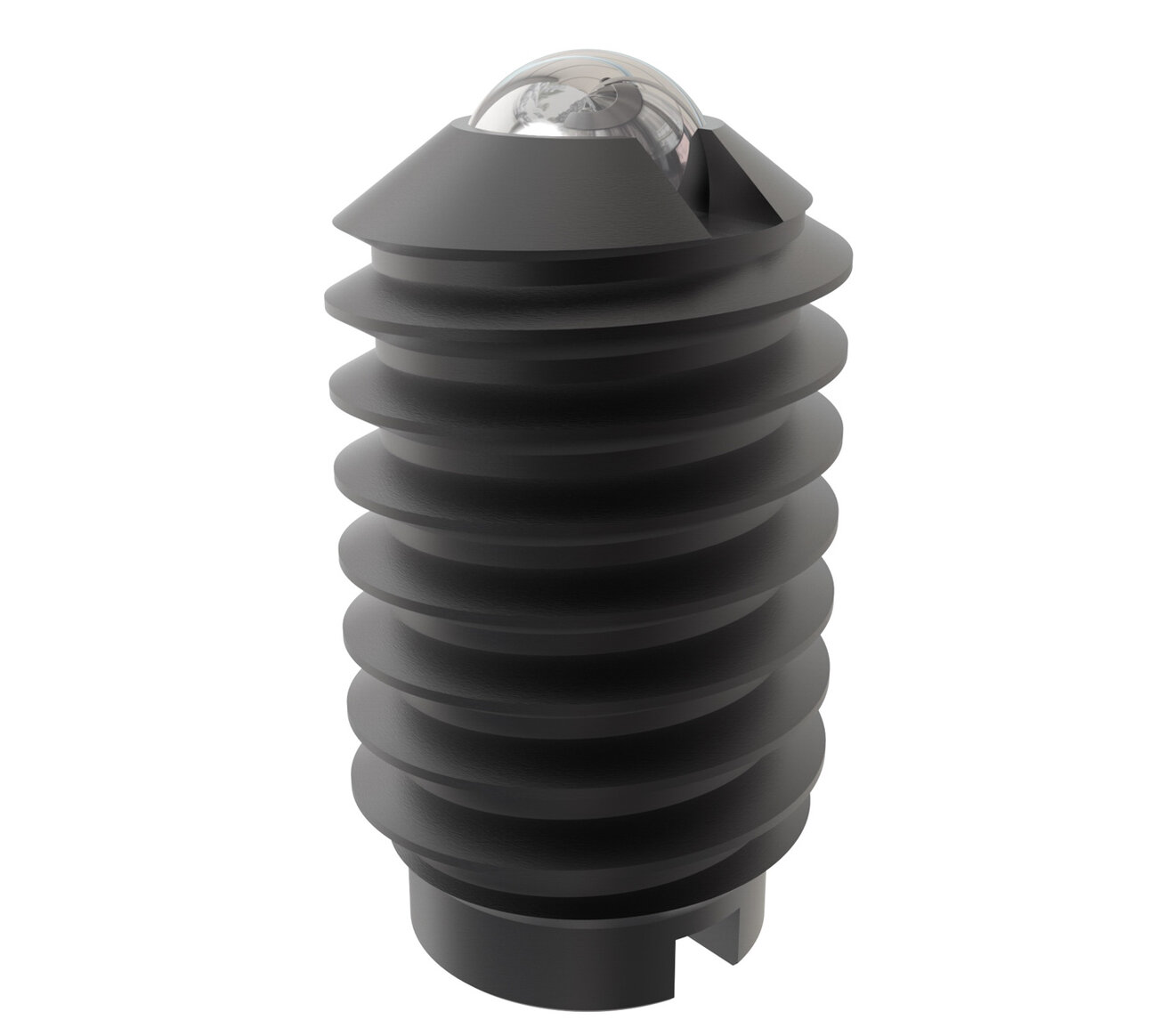
Steel Ball Plungers
Jergens Ball Plungers are made under extremely accurate machine controls and rigid inspection procedures. Accurate spring alignment is maintained by using a stainless rivet with a long shank on larger sizes of our Ball Plungers. This precisely positions the spring for more accurate ball travel and provides positive control of spring pressure. By minimizing the lining pin head thickness, we are able to use the longest possible springs.
Features & Benefits:
-
Positive control of spring pressure
-
Less fatigue and longer spring life by minimizing lining pin head thickness
-
Uniform ball projection keeps variances within ±0.005".
-
Conforms to TCMA dimensional standards
-
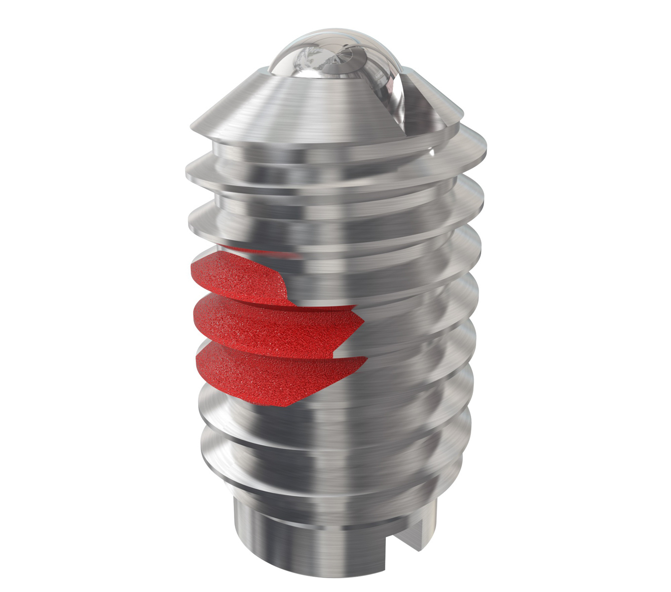
Patch-style locking element
-
Special materials and sizes available upon requests
Material Specifications:
-
Body Material: Low Carbon Steel
-
Ball Material: 440 Stainless Steel
-
Spring Material: 17-7 PH Stainless Steel
-
Body Finish: Black Oxide
-
Thread:
-
Inch: 2A-UNC
-
Metric: Class 6g
-
Note(s):
For easy insertion of Ball Plungers with Locking Elements, the tapped hole should be countersunk at least 0.030"-0.045" (0.76mm-1.14mm) larger than the major diameter of the plunger.
Steel Ball Plungers

Select a part number for CAD drawings, price and stock availability.
| Part Number | CAD | Unit | Thread Size A | Initial Force (lbs) | Final Force (lbs) | B (In) | C (In) | D (In) | Locking Element |
|---|---|---|---|---|---|---|---|---|---|
| 10701 |
|
Inch | 10-24 | 0.50 | 1.50 | 33/64 | 0.025 | 0.093 | Yes |
| 10702 |
|
Inch | 10-24 | 2.00 | 5.00 | 33/64 | 0.025 | 0.093 | Yes |
| 10711 |
|
Inch | 10-24 | 1.50 | 3.00 | 33/64 | 0.025 | 0.093 | Yes |
| 10721 |
|
Inch | 10-24 | 0.50 | 1.50 | 33/64 | 0.025 | 0.093 | No |
| 10722 |
|
Inch | 10-24 | 2.00 | 5.00 | 33/64 | 0.025 | 0.093 | No |
| 10731 |
|
Inch | 10-24 | 1.50 | 3.00 | 33/64 | 0.025 | 0.093 | No |
| 10804 |
|
Inch | 1/4-20 | 2.00 | 4.00 | 17/32 | 0.035 | 0.125 | No |
| 10805 |
|
Inch | 1/4-20 | 3.00 | 7.00 | 17/32 | 0.035 | 0.125 | No |
| 10806 |
|
Inch | 1/4-20 | 4.00 | 12.0 | 17/32 | 0.035 | 0.125 | No |
| 10807 |
|
Inch | 5/16-18 | 2.00 | 4.50 | 37/64 | 0.040 | 0.156 | No |
| 10808 |
|
Inch | 5/16-18 | 4.00 | 9.00 | 37/64 | 0.040 | 0.156 | No |
| 10809 |
|
Inch | 5/16-18 | 6.00 | 17.0 | 37/64 | 0.040 | 0.156 | No |
| 10810 |
|
Inch | 3/8-16 | 2.50 | 5.00 | 5/8 | 0.048 | 0.187 | No |
| 10811 |
|
Inch | 3/8-16 | 5.00 | 10.0 | 5/8 | 0.048 | 0.187 | No |
| 10812 |
|
Inch | 3/8-16 | 6.00 | 21.0 | 5/8 | 0.048 | 0.187 | No |
| 10813 |
|
Inch | 1/2-13 | 3.00 | 6.00 | 3/4 | 0.072 | 0.281 | No |
| 10814 |
|
Inch | 1/2-13 | 6.00 | 12.0 | 3/4 | 0.072 | 0.281 | No |
| 10815 |
|
Inch | 1/2-13 | 6.00 | 30.0 | 3/4 | 0.072 | 0.281 | No |
| 10816 |
|
Inch | 5/8-11 | 4.50 | 9.00 | 1 | 0.096 | 0.375 | No |
| 10817 |
|
Inch | 5/8-11 | 9.00 | 18.0 | 1 | 0.096 | 0.375 | No |
| 10818 |
|
Inch | 5/8-11 | 7.00 | 50.0 | 1 | 0.096 | 0.375 | No |
| 10827 |
|
Inch | 5-40 | 0.25 | 0.75 | 1/4 | 0.020 | 0.062 | No |
| 10904 |
|
Inch | 1/4-20 | 2.00 | 4.00 | 17/32 | 0.035 | 0.125 | Yes |
| 10905 |
|
Inch | 1/4-20 | 3.00 | 7.00 | 17/32 | 0.035 | 0.125 | Yes |
| 10906 |
|
Inch | 1/4-20 | 4.00 | 12.0 | 17/32 | 0.035 | 0.125 | Yes |
| 10907 |
|
Inch | 5/16-18 | 2.00 | 4.50 | 37/64 | 0.040 | 0.156 | Yes |
| 10908 |
|
Inch | 5/16-18 | 4.00 | 9.00 | 37/64 | 0.040 | 0.156 | Yes |
| 10909 |
|
Inch | 5/16-18 | 6.00 | 17.0 | 37/64 | 0.040 | 0.156 | Yes |
| 10910 |
|
Inch | 3/8-16 | 2.50 | 5.00 | 5/8 | 0.048 | 0.187 | Yes |
| 10911 |
|
Inch | 3/8-16 | 5.00 | 10.0 | 5/8 | 0.048 | 0.187 | Yes |
| 10912 |
|
Inch | 3/8-16 | 6.00 | 21.0 | 5/8 | 0.048 | 0.187 | Yes |
| 10913 |
|
Inch | 1/2-13 | 3.00 | 6.00 | 3/4 | 0.072 | 0.281 | Yes |
| 10914 |
|
Inch | 1/2-13 | 6.00 | 12.0 | 3/4 | 0.072 | 0.281 | Yes |
| 10915 |
|
Inch | 1/2-13 | 6.00 | 30.0 | 3/4 | 0.072 | 0.281 | Yes |
| 10916 |
|
Inch | 5/8-11 | 4.50 | 9.00 | 1 | 0.096 | 0.375 | Yes |
| 10917 |
|
Inch | 5/8-11 | 9.00 | 18.0 | 1 | 0.096 | 0.375 | Yes |
| 10918 |
|
Inch | 5/8-11 | 7.00 | 50.0 | 1 | 0.096 | 0.375 | Yes |
| 10927 |
|
Inch | 5-40 | 0.25 | 0.75 | 1/4 | 0.020 | 0.062 | Yes |
| Part Number | CAD | Unit | Thread Size A | Initial Force (kg) | Final Force (kg) | B (mm) | C (mm) | D (mm) | Locking Element |
|---|---|---|---|---|---|---|---|---|---|
| 10871 |
|
Metric | M4 x 0.7 | 0.23 | 0.56 | 9.00 | 0.60 | 2.38 | No |
| 10872 |
|
Metric | M5 x 0.8 | 0.23 | 0.68 | 13.00 | 0.60 | 2.38 | No |
| 10873 |
|
Metric | M5 x 0.8 | 0.68 | 1.35 | 13.00 | 0.60 | 2.38 | No |
| 10874 |
|
Metric | M5 x 0.8 | 0.90 | 2.25 | 13.00 | 0.60 | 2.38 | No |
| 10875 |
|
Metric | M6 x 1.0 | 0.90 | 1.80 | 13.50 | 0.90 | 3.18 | No |
| 10876 |
|
Metric | M6 x 1.0 | 1.35 | 3.15 | 13.50 | 0.90 | 3.18 | No |
| 10877 |
|
Metric | M6 x 1.0 | 1.80 | 5.40 | 13.50 | 0.90 | 3.18 | No |
| 10878 |
|
Metric | M8 x 1.25 | 0.90 | 2.03 | 15.00 | 1.00 | 3.97 | No |
| 10880 |
|
Metric | M8 x 1.25 | 2.70 | 7.65 | 15.00 | 1.00 | 3.97 | No |
| 10881 |
|
Metric | M10 x 1.5 | 1.13 | 2.25 | 16.00 | 1.20 | 4.76 | No |
| 10882 |
|
Metric | M10 x 1.5 | 2.25 | 4.50 | 16.00 | 1.20 | 4.76 | No |
| 10883 |
|
Metric | M10 x 1.5 | 2.70 | 9.45 | 16.00 | 1.20 | 4.76 | No |
| 10886 |
|
Metric | M12 x 1.75 | 2.70 | 13.50 | 19.00 | 2.00 | 7.14 | No |
| 10887 |
|
Metric | M16 x 2.0 | 2.00 | 4.00 | 25.40 | 2.40 | 9.50 | No |
| 10888 |
|
Metric | M16 x 2.0 | 4.00 | 8.10 | 25.40 | 2.40 | 9.50 | No |
| 10889 |
|
Metric | M16 x 2.0 | 3.10 | 22.70 | 25.40 | 2.40 | 9.50 | No |
| 10971 |
|
Metric | M4 x 0.7 | 0.23 | 0.56 | 9.0 | 0.6 | 2.38 | Yes |
| 10972 |
|
Metric | M5 x 0.8 | 0.23 | 0.68 | 13.0 | 0.6 | 2.38 | Yes |
| 10973 |
|
Metric | M5 x 0.8 | 0.68 | 1.35 | 13.0 | 0.6 | 2.38 | Yes |
| 10974 |
|
Metric | M5 x 0.8 | 0.90 | 2.25 | 13.0 | 0.6 | 2.38 | Yes |
| 10975 |
|
Metric | M6 x 1.0 | 0.90 | 1.80 | 13.5 | 0.9 | 3.18 | Yes |
| 10976 |
|
Metric | M6 x 1.0 | 1.35 | 3.15 | 13.5 | 0.9 | 3.18 | Yes |
| 10977 |
|
Metric | M6 x 1.0 | 1.80 | 5.40 | 13.5 | 0.9 | 3.18 | Yes |
| 10978 |
|
Metric | M8 x 1.25 | 0.90 | 2.03 | 15.0 | 1.0 | 3.97 | Yes |
| 10979 |
|
Metric | M8 x 1.25 | 1.80 | 4.05 | 15.0 | 1.0 | 3.97 | Yes |
| 10980 |
|
Metric | M8 x 1.25 | 2.70 | 7.65 | 15.0 | 1.0 | 3.97 | Yes |
| 10981 |
|
Metric | M10 x 1.5 | 1.13 | 2.25 | 16.0 | 1.2 | 4.76 | Yes |
| 10982 |
|
Metric | M10 x 1.5 | 2.25 | 4.50 | 16.0 | 1.2 | 4.76 | Yes |
| 10983 |
|
Metric | M10 x 1.5 | 2.70 | 9.45 | 16.0 | 1.2 | 4.76 | Yes |
| 10984 |
|
Metric | M12 x 1.75 | 1.35 | 2.70 | 19.0 | 2.0 | 7.14 | Yes |
| 10985 |
|
Metric | M12 x 1.75 | 2.70 | 5.40 | 19.0 | 2.0 | 7.14 | Yes |
| 10986 |
|
Metric | M12 x 1.75 | 2.70 | 13.50 | 19.0 | 2.0 | 7.14 | Yes |
| 10987 |
|
Metric | M16 x 2.0 | 2.00 | 4.00 | 25.40 | 2.4 | 9.50 | Yes |
| 10988 |
|
Metric | M16 x 2.0 | 4.00 | 8.10 | 25.40 | 2.4 | 9.50 | Yes |
| 10989 |
|
Metric | M16 x 2.0 | 3.10 | 22.70 | 25.40 | 2.4 | 9.50 | Yes |
Documents and Videos
 Operating Manual
- Operating Manual - 81600 ONLY
- Jergens Production Vise System
- Jergens Production Vises Features and Benefits
- Vertical Machine Solutions
- Horizontal Machine Solutions
- Hydraulic Production Vises
- Production Vises
Related Products
-
Stainless Steel Ball Plungers
-
Stainless Steel Ball Plungers - Fine Thread (UNF)
-
Steel Ball Plungers - Fine Thread (UNF)