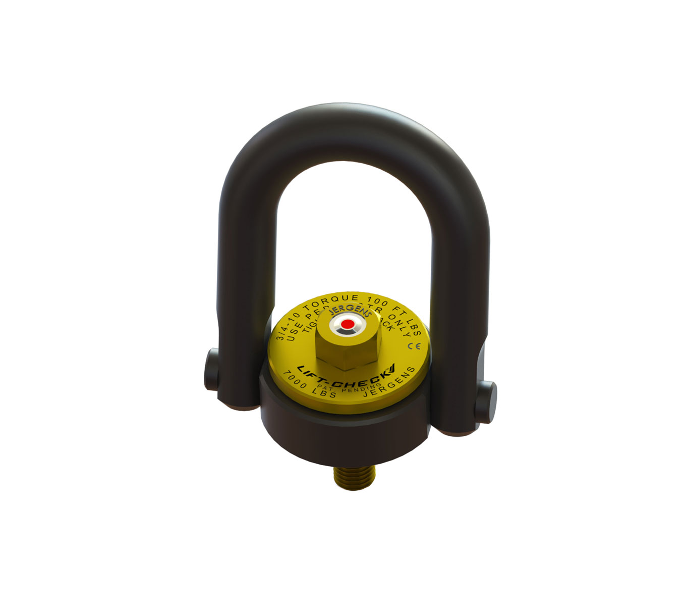
Lift-Check™ Center-Pull Hoist Rings with Long U-Bar
Jergens Lift-Check™ Hoist Rings assure that your application is secure and ready to lift. Lift-Check™ is comprised of a Jergens patented proprietary hex head cap screw which integrates the Visual Tension Indicator.
The Visual Tension Indicator confirms engagement by clearly illustrating whether the bolt joint is loose or tight. Red indicates the bolt joint is loose. Black indicates the bolt joint is tight. This indicator ensures lifting security, provides an accuracy of ±10% of designed tension, provides hands-free inspection at a distance prior to the lift, and reduces installation time. No torque wrench or calibration is needed.
Lift-Check™ Bolts are reusable and provide a reliable visual indication of joint clamping force. Bolt Replacement Kits are available for Jergens Hoist Ring upgrades.
Features, Benefits, & Product Specifications:
-
Material: Alloy Steel
-
Finish: Black Oxide
-
Temperature Range: -4°F to 168°F (-20°C to 75°C)
-
Washer:
-
Inch: Zinc Plated with Yellow/Gold Color Conversion Coating
-
Metric: Zinc Plated with Clear/Silver Color Conversion Coating
-
-
Full 360° swivel and 180° pivot action
-
Proof tested to 200% of its rated load capacity
-
Rated at a 5:1 strength factor
-
Made in the U.S.A.
-
CE Certified
-
U-bar, bolt, pins, base, washer, and bushing are Magnetic Particle Inspected
-
Conforms to ASME B30.26 and Mil-STD-209K
Note: * Rated load may be reduced at 90° from vertical.
If requesting large quantities or high volume please contact customer service via [email protected] or (866) 594-5565. For a self-service alternative, try our Quick Quote form!
Lift-Check™ Center-Pull Hoist Rings with Long U-Bar


Select a part number for CAD drawings, price and stock availability.
| Part Number | CAD | Unit | Thread Size A | Load Capacity | B (In) | Thread Length C (In) | D (In) | E (In) | F (In) | G (In) | Std U-Bar H (In) | Torque (ft. lbs.) | Weight (lbs) | Bolt Kit Part Number |
|---|---|---|---|---|---|---|---|---|---|---|---|---|---|---|
| 23511LC |
|
Inch | 1/2-13 In | 2500 lbs | 4.78 | 3/4 | 1.50 | 0.88 | 0.75 | 3.52 | 4 3/8 | 28 | 2.5 | 23611LC |
| 23512LC |
|
Inch | 1/2-13 In | 2500 lbs | 6.72 | 1 | 1.50 | 0.88 | 0.75 | 3.52 | 4 3/8 | 28 | 2.5 | 23612LC |
| 23513LC |
|
Inch | 1/2-13 In | 2500 lbs | 6.72 | 1 1/4 | 1.50 | 0.88 | 0.75 | 3.52 | 4 3/8 | 28 | 2.5 | 23613LC |
| 23514LC |
|
Inch | 5/8-11 In | 4000 lbs | 6.72 | 1 | 1.50 | 0.88 | 0.75 | 3.52 | 4 11/32 | 60 | 2.7 | 23614LC |
| 23515LC |
|
Inch | 5/8-11 In | 4000 lbs | 6.72 | 1 1/4 | 1.50 | 0.88 | 0.75 | 3.52 | 4 11/32 | 60 | 2.7 | 23615LC |
| 23516LC |
|
Inch | 5/8-11 In | 4000 lbs | 6.72 | 1 1/4 | 1.50 | 0.88 | 0.75 | 3.52 | 4 11/32 | 60 | 2.7 | 23616LC |
| 23517LC |
|
Inch | 3/4-10 In | 5000 lbs | 6.72 | 1 | 1.50 | 0.88 | 0.75 | 3.52 | 4 3/16 | 100 | 3.0 | 23617LC |
| 23518LC |
|
Inch | 3/4-10 In | 5000 lbs | 6.72 | 1 1/2 | 1.50 | 0.88 | 0.75 | 3.52 | 4 3/16 | 100 | 3.0 | 23618LC |
| 23520LC |
|
Inch | 3/4-10 In | 7000 lbs | 8.11 | 1 | 2.31 | 1.40 | 1.00 | 5.14 | 4 3/16 | 100 | 6.8 | 23620LC |
| 23521LC |
|
Inch | 3/4-10 In | 7000 lbs | 8.11 | 1 1/2 | 2.31 | 1.40 | 1.00 | 5.14 | 4 3/16 | 100 | 6.8 | 23621LC |
| 23523LC |
|
Inch | 7/8-9 In | 8000 lbs | 8.11 | 1 | 2.31 | 1.40 | 1.00 | 5.14 | 4 9/16 | 160 | 7.0 | 23623LC |
| 23524LC |
|
Inch | 7/8-9 In | 8000 lbs | 8.11 | 1 1/4 | 2.31 | 1.40 | 1.00 | 5.14 | 4 9/16 | 160 | 7.0 | 23624LC |
| 23525LC |
|
Inch | 1-8 In | 10000 lbs | 8.11 | 1 1/4 | 2.31 | 1.40 | 1.00 | 5.14 | 4 15/32 | 230 | 7.3 | 23625LC |
| 23526LC |
|
Inch | 1-8 In | 10000 lbs | 8.11 | 1 1/2 | 2.31 | 1.40 | 1.00 | 5.14 | 4 15/32 | 230 | 7.3 | 23626LC |
| 23527LC |
|
Inch | 1-8 In | 10000 lbs | 8.11 | 2 1/4 | 2.31 | 1.40 | 1.00 | 5.14 | 4 15/32 | 230 | 7.3 | 23627LC |
| Part Number | CAD | Unit | Thread Size A | Load Capacity | B (mm) | Thread Length C (mm) | D (mm) | E (mm) | F (mm) | G (mm) | Std U-Bar H (mm) | Torque (Nm) | Weight (kgs) | Bolt Kit Part Number |
|---|---|---|---|---|---|---|---|---|---|---|---|---|---|---|
| 23562LC |
|
Metric | M12 x 1.75 | 1050 kgs | 170.7 | 19 | 38.1 | 22.4 | 19 | 89.4 | 114 | 37 | 1.1 | 23662LC |
| 23565LC |
|
Metric | M16 x 2.0 | 1700 kgs | 170.7 | 29 | 38.1 | 22.4 | 19 | 89.4 | 111 | 80 | 1.1 | 23665LC |
| 23568LC |
|
Metric | M20 x 2.5 | 2150 kgs | 170.7 | 34 | 38.1 | 22.4 | 19 | 89.4 | 108 | 135 | 1.2 | 23668LC |
| 23571LC |
|
Metric | M20 x 2.5 | 3000 kgs | 203.0 | 32 | 58.7 | 35.6 | 25.4 | 130.6 | 119 | 135 | 3.1 | 23671LC |
| 23574LC |
|
Metric | M24 x 3.0 | 4200 kgs | 203.0 | 37 | 58.7 | 35.6 | 25.4 | 130.6 | 117 | 305 | 3.2 | 23674LC |
Documents and Videos
 Operating Manual
- Operating Manual - 81600 ONLY
- Jergens Production Vise System
- Jergens Production Vises Features and Benefits
- Vertical Machine Solutions
- Horizontal Machine Solutions
- Hydraulic Production Vises
- Production Vises