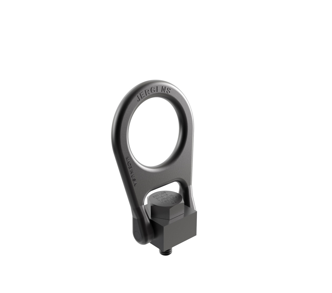
Forged Center-Pull Hoist Rings
Jergens Forged Center-Pull Hoist Rings integrate a solid center brace lift bail into our most popular style of product. This design replaces the use of stationary eyebolts and eliminates the possibility of spreading the lift ring in misapplications. Forged Center-Pull Hoist Rings are ideal for OEM applications such as lifting tooling columns and large fixtures.
|
Features, Benefits, & Product Specifications:
|
 |
Note(s):
- The rated load may be reduced at 90° from vertical for Inch Part No.'s 23914 & 23915 and Metric Part No.'s 23974, 23978, & 23979.
If requesting large quantities or high volume please contact customer service via [email protected] or (866) 594-5565. For a self-service alternative, try our Quick Quote form!
Forged Center-Pull Hoist Rings


Select a part number for CAD drawings, price and stock availability.
| Part Number | CAD | Unit | Thread Size | Load Capacity | Bail Type | B (In) | C (In) | D (In) | E (In) | F (In) | G (In) | H (In) | I (In) | J (In) | K (In) | L (In) | Hex Size M | Torque (ft. lbs.) | Weight (lbs) |
|---|---|---|---|---|---|---|---|---|---|---|---|---|---|---|---|---|---|---|---|
| 23906 |
|
Inch | 5/16-18 In | 800 lbs | Ring | 3/64 | 15/32 | 1/2 | 1 | 1 | 11/32 | 1/4 | 1 1/2 | 2 1/4 | 2 15/32 | 3 19/32 | 3/4 | 7 | 0.6 |
| 23907 |
|
Inch | 5/16-18 In | 800 lbs | Ring | 3/64 | 5/8 | 1/2 | 1 | 1 | 11/32 | 1/4 | 1 1/2 | 2 1/4 | 2 15/32 | 2 15/32 | 3/4 | 7 | 0.6 |
| 23908 |
|
Inch | 3/8-16 In | 1000 lbs | Ring | 3/64 | 9/16 | 1/2 | 1 | 1 | 11/32 | 1/4 | 1 1/2 | 2 1/4 | 2 15/32 | 3 19/32 | 3/4 | 12 | 0.6 |
| 23909 |
|
Inch | 3/8-16 In | 1000 lbs | Ring | 3/64 | 3/4 | 1/2 | 1 | 1 | 11/32 | 1/4 | 1 1/2 | 2 1/4 | 2 15/32 | 3 19/32 | 3/4 | 12 | 0.6 |
| 23910 |
|
Inch | 1/2-13 In | 2500 lbs | Ring | 1/16 | 11/16 | 1 | 2 | 1 1/2 | 9/16 | 3/4 | 3 | 4 7/16 | 4 | 6 3/8 | 1 1/4 | 28 | 3.6 |
| 23911 |
|
Inch | 1/2-13 In | 2500 lbs | Ring | 1/16 | 1 | 1 | 2 | 1 1/2 | 9/16 | 3/4 | 3 | 4 7/16 | 4 | 6 3/8 | 1 1/4 | 28 | 3.6 |
| 23914 |
|
Inch | 5/8-11 In | 4000 lbs | Ring | 1/16 | 15/16 | 1 | 2 | 1 1/2 | 9/16 | 3/4 | 3 | 4 7/16 | 4 | 6 3/8 | 1 1/4 | 60 | 3.6 |
| 23915 |
|
Inch | 5/8-11 In | 4000 lbs | Ring | 1/16 | 1 1/4 | 1 | 2 | 1 1/2 | 9/16 | 3/4 | 3 | 4 7/16 | 4 | 6 3/8 | 1 1/4 | 60 | 3.6 |
| 23917 |
|
Inch | 3/4-10 In | 5000 lbs | Ring | 1/16 | 1 1/8 | 1 | 2 | 1 1/2 | 9/16 | 3/4 | 3 | 4 7/16 | 4 | 6 3/8 | 1 1/4 | 100 | 3.6 |
| 23918 |
|
Inch | 3/4-10 In | 5000 lbs | Ring | 1/16 | 1 1/2 | 1 | 2 | 1 1/2 | 9/16 | 3/4 | 3 | 4 7/16 | 4 | 6 3/8 | 1 1/4 | 100 | 3.6 |
| 23926 |
|
Inch | 1-8 In | 10000 lbs | Large | 1/16 | 1 1/2 | 1 7/8 | 3 25/32 | 3 | 1 1/16 | 1 1/4 | 3 19/32 | 5 13/16 | 8 5/32 | 9 21/32 | 2 1/2 | 230 | 15.7 |
| 23927 |
|
Inch | 1-8 In | 10000 lbs | Large | 1/16 | 2 | 1 7/8 | 3 | 25/32 | 3 | 1 1/16 | 1 1/4 | 5 13/16 | 8 5/32 | 9 21/32 | 2 1/2 | 230 | 15.9 |
| 23929 |
|
Inch | 1-1/4-7 In | 15000 lbs | Large | 1/16 | 1 7/8 | 1 7/8 | 3 25/32 | 3 | 1 1/16 | 1 1/4 | 3 19/32 | 5 13/16 | 8 5/32 | 9 21/32 | 2 1/2 | 470 | 16 |
| 23930 |
|
Inch | 1-1/4-7 In | 15000 lbs | Large | 1/16 | 2 1/2 | 1 7/8 | 3 25/32 | 3 | 1 1/16 | 1 1/4 | 3 19/32 | 5 13/16 | 8 5/32 | 9 21/32 | 2 1/2 | 470 | 16.2 |
| 23933 |
|
Inch | 1-1/2-6 In | 24000 lbs | Large | 7/64 | 2 1/4 | 2 1/2 | 4 7/8 | 4 1/2 | 1 7/16 | 1 3/4 | 4 1/2 | 7 23/32 | 11 7/16 | 13 27/32 | 3 1/4 | 800 | 42.3 |
| 23934 |
|
Inch | 1-1/2-6 In | 24000 lbs | Large | 7/64 | 3 | 2 1/2 | 4 7/8 | 4 1/2 | 1 7/16 | 1 3/4 | 4 1/2 | 7 23/32 | 11 7/16 | 13 27/32 | 3 1/4 | 800 | 42.7 |
| 23935 |
|
Inch | 2-4 1/2 In | 30000 lbs | Large | 7/64 | 3 | 2 1/2 | 4 7/8 | 4 1/2 | 1 7/16 | 1 3/4 | 4 1/2 | 7 23/32 | 11 7/16 | 13 27/32 | 3 1/4 | 800 | 43.8 |
| 23936 |
|
Inch | 2-4 1/2 In | 30000 lbs | Large | 7/64 | 4 | 2 1/2 | 4 7/8 | 4 1/2 | 1 7/16 | 1 3/4 | 4 1/2 | 7 23/32 | 11 7/16 | 13 27/32 | 3 1/4 | 800 | 44.7 |
| Part Number | CAD | Unit | Thread Size | Load Capacity | Bail Type | B (mm) | C (mm) | D (mm) | E (mm) | F (mm) | G (mm) | H (mm) | I (mm) | J (mm) | K (mm) | L (mm) | Hex Size M | Torque (Nm) | Weight (kgs) |
|---|---|---|---|---|---|---|---|---|---|---|---|---|---|---|---|---|---|---|---|
| 23934 |
|
||||||||||||||||||
| 23956 |
|
Metric | M8 x 1.25 | 400 kgs | Ring | 1.2 | 12 | 12.7 | 25.4 | 25.4 | 8.7 | 6.3 | 38.1 | 57.2 | 62.7 | 91.3 | 19 | 10 | 0.27 |
| 23958 |
|
Metric | M10 x 1.5 | 450 kgs | Ring | 1.2 | 15 | 12.7 | 25.4 | 25.4 | 8.7 | 6.3 | 38.1 | 57.2 | 62.7 | 91.3 | 19 | 17 | 0.27 |
| 23962 |
|
Metric | M12 x 1.75 | 1050 kgs | Ring | 1.6 | 18 | 25.4 | 50.8 | 38.1 | 14.3 | 19 | 76.2 | 112.7 | 101.6 | 161.9 | 32 | 37 | 1.64 |
| 23965 |
|
Metric | M16 x 2.0 | 1900 kgs | Ring | 1.6 | 24 | 25.4 | 50.8 | 38.1 | 14.3 | 19 | 76.2 | 112.7 | 101.6 | 161.9 | 32 | 80 | 1.64 |
| 23968 |
|
Metric | M20 x 2.5 | 2150 kgs | Ring | 1.6 | 30 | 25.4 | 50.8 | 38 1/10 | 14.3 | 19 | 76.2 | 112.7 | 101.6 | 161.9 | 32 | 134 | 1.7 |
| 23974 |
|
Metric | M24 x 3.0 | 4200 kgs | Large | 1.6 | 35.7 | 47.6 | 96 | 76.2 | 27 | 31.7 | 91.3 | 147.6 | 207.2 | 245.3 | 63.5 | 305 | 7.1 |
| 23975 |
|
Metric | M24 x 3.0 | 4200 kgs | Large | 1.6 | 47.6 | 47.6 | 96 | 76.2 | 27 | 31.7 | 91.3 | 147.6 | 207.2 | 245.3 | 63.5 | 305 | 7.2 |
| 23978 |
|
Metric | M30 x 3.5 | 7000 kgs | Large | 1.6 | 44.8 | 47.6 | 96 | 76.2 | 27 | 31.7 | 91.3 | 147.6 | 207.2 | 245.3 | 63.5 | 590 | 7.3 |
| 23979 |
|
Metric | M30 x 3.5 | 7000 kgs | Large | 1.6 | 60 | 47.6 | 96 | 76.2 | 27 | 31.7 | 91.3 | 147.6 | 207.2 | 245.3 | 63.5 | 590 | 7.4 |
| 23982 |
|
Metric | M36 x 4.0 | 11000 kgs | Large | 2.8 | 53.6 | 63.5 | 123.8 | 114 3/16 | 36.5 | 44.5 | 114.3 | 196.1 | 290.5 | 351.6 | 82.55 | 960 | 19.1 |
| 23983 |
|
Metric | M36 x 4.0 | 11000 kgs | Large | 2.8 | 71.4 | 63.5 | 123.8 | 114.3 | 36.5 | 44.5 | 114.3 | 196.1 | 290.5 | 351.6 | 82.55 | 960 | 19.3 |
| 23984 |
|
Metric | M42 x 4.5 | 12500 kgs | Large | 2.8 | 62.7 | 63.5 | 123.8 | 114.3 | 36.5 | 44.5 | 114.3 | 196.1 | 290.5 | 351.6 | 82.55 | 980 | 19.4 |
| 23985 |
|
Metric | M42 x 4.5 | 12500 kgs | Large | 2.8 | 83.3 | 63.5 | 123.8 | 114.3 | 36.5 | 44.5 | 114.3 | 196.1 | 290.5 | 351.6 | 82.55 | 980 | 19.6 |
| 23986 |
|
Metric | M48 x 5.0 | 13500 kgs | Large | 2.8 | 71.4 | 63.5 | 123.8 | 114.3 | 36.5 | 44.5 | 114.3 | 196.1 | 290.5 | 351.6 | 82.55 | 980 | 19.7 |
Documents and Videos
 Operating Manual
- Operating Manual - 81600 ONLY
- Jergens Production Vise System
- Jergens Production Vises Features and Benefits
- Vertical Machine Solutions
- Horizontal Machine Solutions
- Hydraulic Production Vises
- Production Vises